Using Collision Detection to Place Non-Intersecting Items in a CAD file
Problem Description
For legibility and presentation purposes, we would like to programmatically append a descriptive label to an item in a CAD file in such a way that it doesn’t collide with the any preexisting labels/items.
Illustrative Example
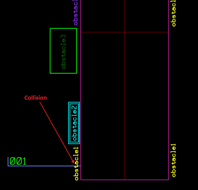
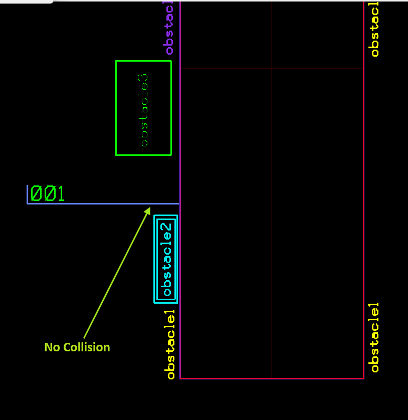
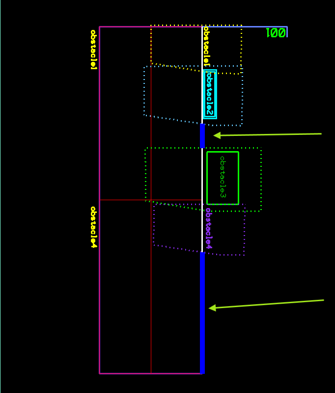
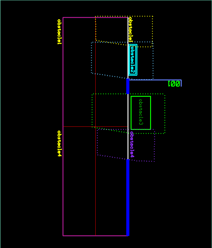
Given a CAD drawing of a set of cells with multiple labels placed on the side. Programmatically place a new label “001” without intersecting any existing labels/objects. See images below.
Collision between the “001” label and obstacle1
No collision between the “001” label and existing obstacles
Introduction
To achieve a collision-free placement of the new label for the example above, we’re using a concept in Computational Geometry called Minkowski Sums. The concept of Minkowski Sums of two polygons is defined as a set of points extracted by summing all pairs of points from the 2 polygons.
After creating a concave hull (C.H) for each obstacle and the new label, we’re convolving the C.H of the new label with the C.H of each obstacle at 0,0 origin and 180°. The result of the convolution will represent the collision space for each obstacle and the new label can be placed anywhere outside of the collision space.
Computing the collision-free space for the “001” label in the example above
Summary of the computation steps:
- Extract the main placement line
- Compute Minkowski Sums between label and obstacles at 0,0 org and at 180°
- Clip the resulting polygons from Minkowski Sums from the main placement line
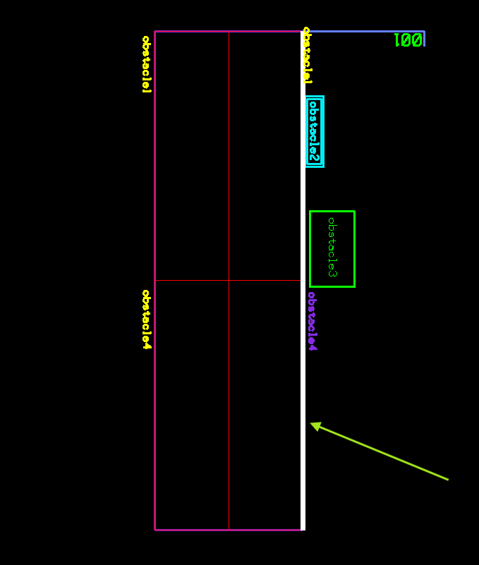
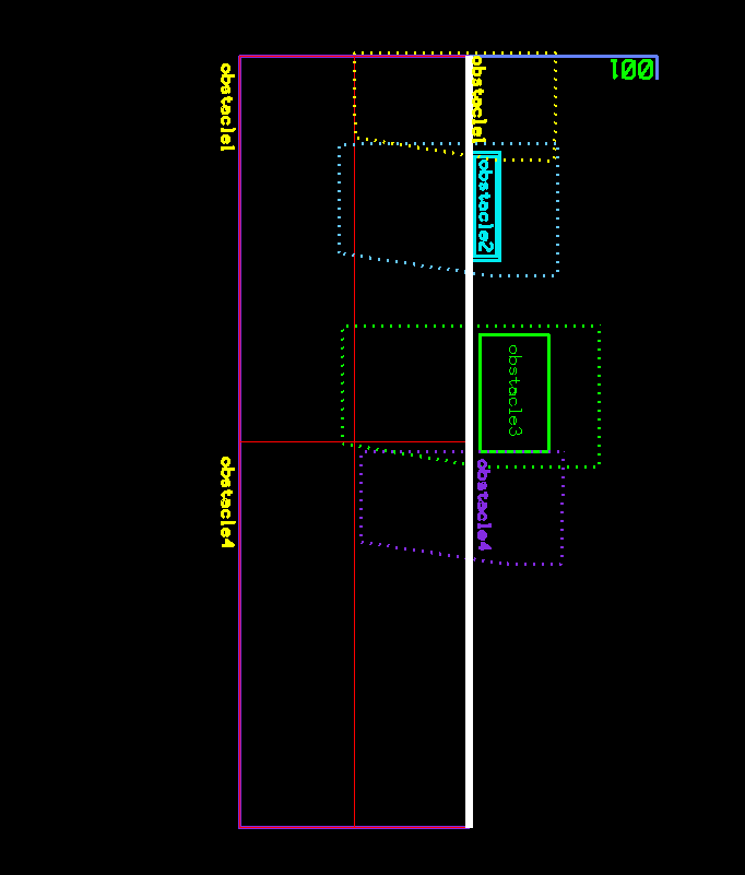
First step is to extract the main placement line (shown in white below) that represents all possible placement points, with or without collision with any existing objects. Next step is to compute the Minkowski Sums of the “001” label with each obstacle at zero origin and at 180°. Results are shown in dashed polygons in the image below. As explained before, the resulting shapes represent the collision space therefore they need to be clipped out of the main placement line (white line). All the other points on the main placement line will be valid candidates for collision-free placement. For simplicity, we will pick the point closest to beginning of the side line.
Main placement line shown in White
Dashed polygons representing Minkowski Sums of label and each obstacle
Collision-free space shown in blue
Placement of label on collision-free space
Sample code
/***************************************
  Descr: Returns the Minkowski Sums between a robot and and set of obstacles
****************************************/
int mcs_minkowskiSums
(
 VecMsPoints			vRobotPts,		//  => flag hull pts [MU]
 vector<VecMsPoints>	vvObstaclePts,  //  => obstacle pts [MU]
 vector<VecMsPoints>&	rvvMinSums		// <=
)
{
	polygon_set a, b, c;
	polygon poly;
	std::vector<point> pts_robot;

	removeObstacleIntersections(vvObstaclePts);

  // Convert robot points to UORs only necessary if you're using MDL (Bentley uStation)
	int index =0;
	for each (DPoint3d pt in vRobotPts) // convert to UORs
	{
		DPoint3d	dPt;
		Point3d		iPt;

		dPt.x = mdlCnv_masterUnitsToUors(pt.x);
		dPt.y = mdlCnv_masterUnitsToUors(pt.y);
		dPt.z = 0.0;

		mdlCnv_DPointToIPoint (&iPt, &dPt);
		pts_robot.push_back(point(iPt.x,iPt.y));
	}

	boost::polygon::set_points(poly, pts_robot.begin(), pts_robot.end());
	//boost::geometry::correct(poly);
	poly.size();
	a += poly;

	for each (VecMsPoints vObstaclePts in vvObstaclePts)
	{
	  // Convert obtscale points to UORs. ** only necessary if you're using MDL (Bentley uStation)
		polygon poly1;
		std::vector<point> pts;
		for each (DPoint3d pt in vObstaclePts) // convert to UORs and * -1 for Mink Diff
		{
			DPoint3d	dPt;
			Point3d		iPt;

			dPt.x = mdlCnv_masterUnitsToUors(pt.x) * -1.0;
			dPt.y = mdlCnv_masterUnitsToUors(pt.y) * -1.0;
			dPt.z = 0.0;

			mdlCnv_DPointToIPoint (&iPt, &dPt);

			pts.push_back(point(iPt.x,iPt.y));
		}

		boost::polygon::set_points(poly1, pts.begin(), pts.end());
		//boost::geometry::correct(poly1);
		poly1.size();
		b += poly1;
	}

	convolve_two_polygon_sets(c, a, b); // From Boost

	if (c.size() == 0)
		return FALSE;
	if (c.empty())
		return FALSE;

	//printf("\n BEFORE SIMPLE POLYGONS");
	//SimplePolygons simplePolygons;
	using namespace boost::polygon;
	vector<polygon> resultPolygons;
	c.get(resultPolygons);

	//for each(SimplePolygon poly in simplePolygons)
	for each(polygon poly in resultPolygons)
		rvvMinSums.push_back(mcs_get_points_poly(begin_points(poly), end_points(poly)));

	return TRUE;
}
Conclusion
We have shown in this post how to automatically add a new item to a CAD file without collision with existing items. We used Minkowski Sums for obstacle detection in a CAD file . The application of this concept can however extend beyond CAD/Collision Detection and can be used in numerous other fields such as robot motion, 3D modeling, … etc
Helpful links:
https://cp-algorithms.com/geometry/minkowski.html
https://www.boost.org/doc/libs/develop/libs/polygon/doc/gtl_minkowski_tutorial.htm

