Polygons

Introduction to Marshaling in C#

Posted by Nabil Kherouf
on December 3, 2024
Comments Off on Introduction to Marshaling in C#

Using Marshaling to Pass Data between
C# and Native Code (C/C++, Fortran)

Introduction

Does your C#/VB.NET managed code program need to call unmanaged (legacy) code routines in DLL‘s written in C/C++, Fortran, or Assembler

We found ourselves writing a C# program for a customer and needed to call analysis routines in a thermodynamics library called REFPROP which was written in Fortran and compiled with the C-Runtime library. The REFPROP routines expect character, integer, double arrays of data passed as both inputs and outputs. Types can be different (size, allocation, structure…etc) between managed and unmanaged code and hence the main need for marshaling as explained in this post. The following images show a Fortran method wrapped and invoked from within a C# program:

WMOLdll method being called in C#
Importing the WMOLdll method from the Fortran library

Overview

Marshaling in C# is the process of converting data between different languages and environments. One of its most important aspects is managing the data to be passed from unmanaged code to managed code and vice versa. Managed code is code that is handled by a runtime environment such as CLR (Common Language Runtime) whereas unmanaged code is code that is run directly on the hardware and outside any runtime environment. In C#, marshaling is often used to interact with native code, such as code written in C/C++ or Fortran. In this article, we will explain the basics of marshaling in C# and provide examples of how to make use of it.

Why is Marshaling needed ?

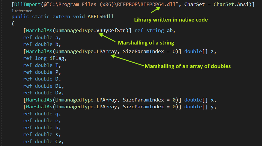
Marshaling is needed because the data types and memory are handled very differently between managed and unmanaged code. For example, a typical C-Runtime routine takes as both input/output a pointer to an array of characters, whereas C# provides a string class which does not give access to pointers. Thus, a mechanism is needed to pass data between managed and unmanaged environments. Types of parameters which do not require any conversion/marshaling, for instance int, double, byte, long, are called Blittable. Marshaling for Non-Blittable types in C# is achieved using the MarshalAs attribute. See example below:

Invoking a Fortran method “ABFLSHdll” from C#
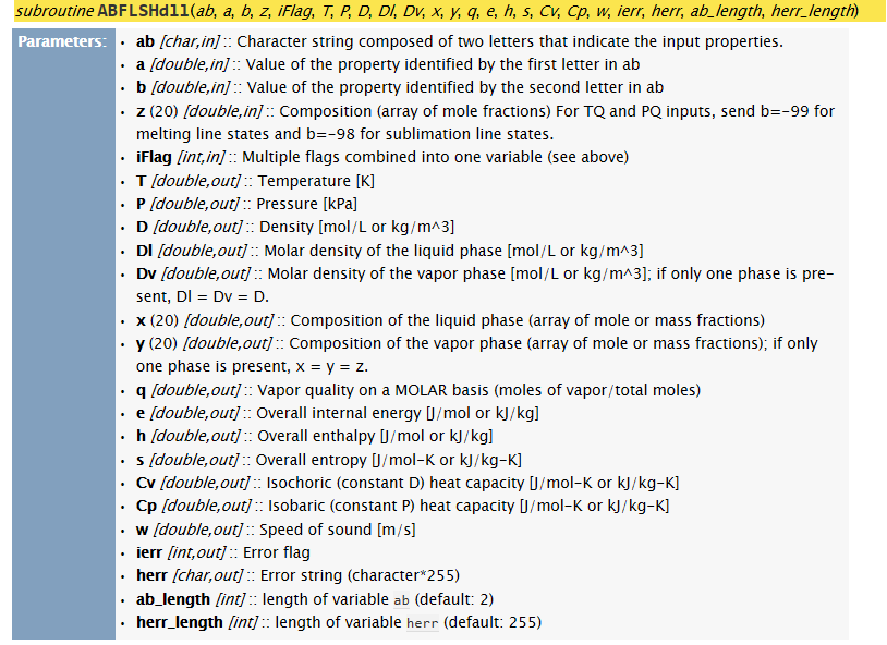
Input/output parameters of “ABFLSHdll” in Fortran

Examples

To achieve marshaling in managed code (C#), we have to use the MarshalAsAttribute attribute. It can be applied to either fields of a class, parameters, or return values of a method:

Marshaling of a parameter of a method:

[DllImport(@"C:\Program Files (x86)\REFPROP\REFPRP64.dll", CharSet = CharSet.Ansi)]
public static extern void ABFLSHdll
(
    [MarshalAs(UnmanagedType.VBByRefStr)] ref string ab,
    ref double a,
    ref double b,
    [MarshalAs(UnmanagedType.LPArray, SizeParamIndex = 0)] double[] z,
    ref long iFlag,
    ref double T,
    ref double P,
    ref double D,
    ref double Dl,
    ref double Dv,
    [MarshalAs(UnmanagedType.LPArray, SizeParamIndex = 0)] double[] x,
    [MarshalAs(UnmanagedType.LPArray, SizeParamIndex = 0)] double[] y,
    ref double q,
    ref double e,
    ref double h,
    ref double s,
    ref double Cv,
    ref double Cp,
    ref double w,
    ref long ierr,
    [MarshalAs(UnmanagedType.VBByRefStr)] ref string herr,
    ref long ab_length,
    ref long herr_length
 );


In the code above, the ABFLSHdll routine is being imported (first line) from a library (REFPRP64.dll) written in Fortran and takes strings and arrays among other types which don’t need to be marshaled in-between native and managed code namely: double, int, long parameters. The first parameter is a string and is being marshaled using [MarshalAs(UnmanagedType.VBByRefStr)]. The method also expects an array of doubles for the fourth parameter and is being marshaled using [MarshalAs(UnmanagedType.LPArray, SizeParamIndex = 0)].

Marshaling of a return value of a method:

[return: MarshalAs(UnmanagedType.LPWStr)]
public String SaySomething()
{
    return "Hello World";
}


The return value of type String of the the function “SaySomething” above is marshaled using the keyword return: and the attribute MarshalAs(UnmanagedType.LPWStr).

Marshaling of a field of a class:

class MyClass {
    [MarshalAs(UnmanagedType.LPWStr)]
    public String msg = "Hello World";
}


The member field msg in the class above is marshaled using [MarshalAs(UnmanagedType.LPWStr)].

Conclusion

We’ve briefly explained Marshaling in this article and provided a few examples on how to do it in C#. As stated above, not all types need to be marshaled when importing unmanaged code. The MarshalAsAttribute is therefore optional as each data type has a default marshaling mechanism and the attribute is only necessary when a given type can be marshaled to multiple types within an environment.

Mill Creek Systems, Inc provides software development services in this area. If you have any software needs, please reach out to us by clicking on the “Contact us” button below.

Contact us

Helpful links

Type marshaling in C#: https://learn.microsoft.com/en-us/dotnet/standard/native-interop/type-marshalling

Blittable and Non-Blittable types: https://learn.microsoft.com/en-us/dotnet/framework/interop/blittable-and-non-blittable-types

Common Language Runtime: https://learn.microsoft.com/en-us/dotnet/standard/clr?redirectedfrom=MSDN

Continue Reading

Using Voronoi Diagrams to Equally Divide/Allocate Space Between Polygons

Posted by Nabil Kherouf
on October 28, 2024
Comments Off on Using Voronoi Diagrams to Equally Divide/Allocate Space Between Polygons

Using Voronoi Diagrams to Equally Divide/Allocate Space Between Polygons

Problem description

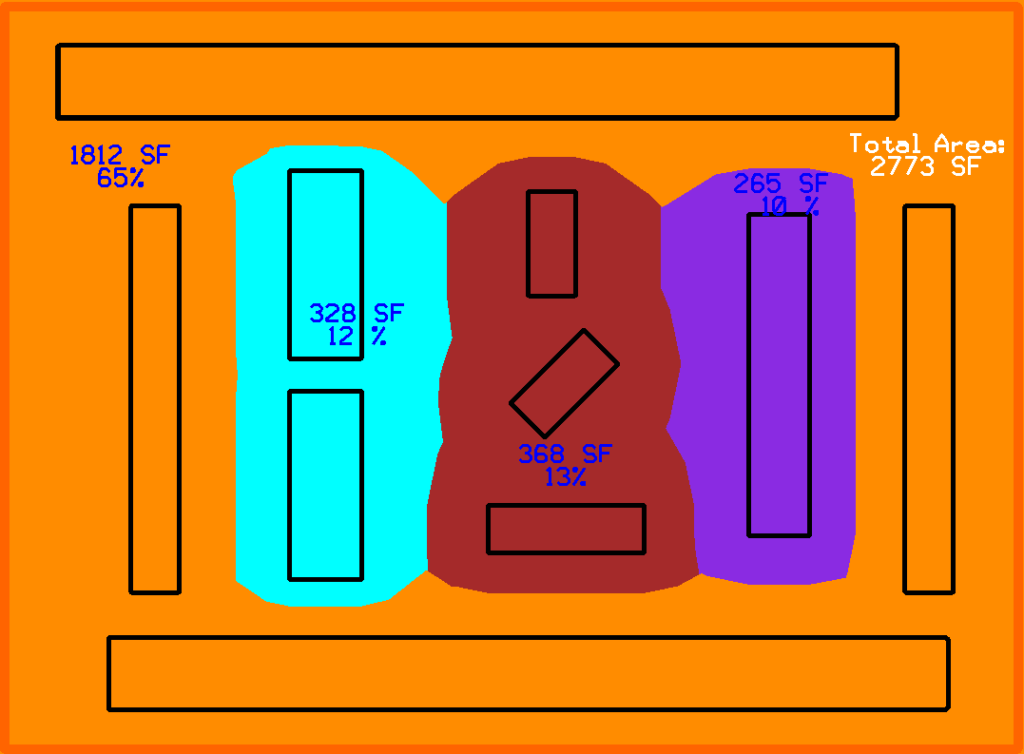
Given a set of arbitrary polygons belonging to different categories, we want to equally divide the space between the polygons and compute the square footage of each category. For example, given different categories of machines on a factory floor; for each category, we need to sum up the area of each machine polygon and its buffer zone and determine its percent in relation to the total factory floor area.

The following images show a set of polygons in different color-coded categories.

Arbitrary polygons with different color-coded categories.
Desired buffer polygons for each category.
Square footage of each category by percent of total area.

Introduction

We tried several approaches to compute the square footage including expanding the polygons until they intersect with each other and sending rays outward from each polygon to find midpoints with direct neighbors. Neither of the two approaches was successful. We needed an algorithm to find the buffer zone for each polygon in such a way that it divides the space equally between all adjacent polygons.

How to divide space between a set of polygons

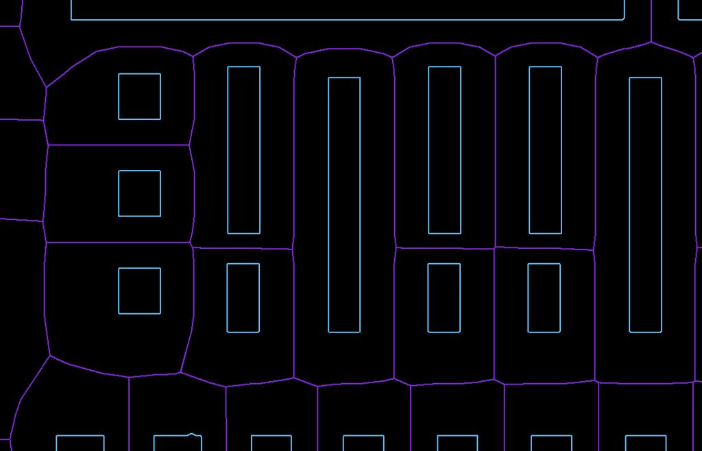
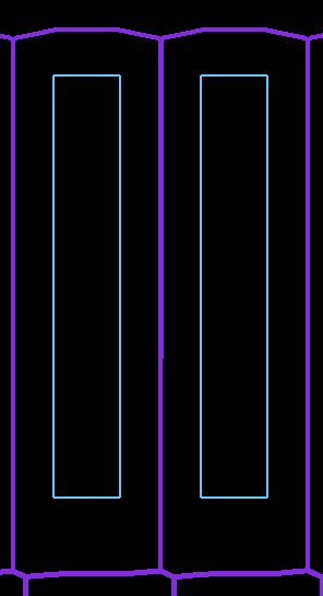
We found a concept in computational geometry called Voronoi Diagrams. This allowed us to generate a set of midpoints between each polygon and all of its neighboring polygons. By creating a shape from the set of midpoints, we would find the center lines for each polygon as shown in the image below:

Purple polygons from Voronoi diagrams equally divided the space between polygons

Voronoi Diagrams

The simplest definition of Voronoi Diagrams is it being the partition of a plane into a set of regions close to each of a set of objects (seeds). In other words, given a set of seeds in a plane, a Voronoi region/cell of a seed is an area encompassing points closer to that seed than any other.

5 seeds and their Voronoi cells

To use Voronoi Diagrams with a set of polygons, we need to compute a cell for each segment of a given polygon. By performing a union on the resulting Voronoi cells for each polygon, we find the center lines between the polygon and its direct neighbors (See examples below).

Following image shows a Voronoi cell for each segment with matching colors:

Voronoi Cells/Segments with matching colors

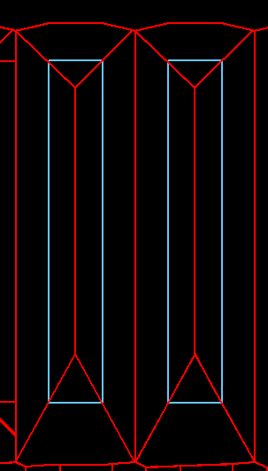
Following images show the Voronoi cells (in red) for each segment of two adjacent polygons and the final center lines in purple after performing the union of the Voronoi cells for each polygon:

All Voronoi cells (in red) for each
polygon
Voronoi cells combined with geometric
union to form center lines (in purple)

While performing a geometric union of the output Voronoi cells that resulted in center lines, we determined these center lines could be useful for other purposes such as navigation, routing, etc.

Step-by-step process of finding the center lines

  1. Extract endpoints of all polygon segments
  2. Assign segments a unique id to associate them with their original polygon
  3. Use Boost Geometry Library to compute Voronoi cells for each segment
  4. Identify all segments of the same polygon and perform a boolean union of the cells associated with them

The Boost Library provides a very efficient and easy-to-use function to compute the Voronoi Diagrams of any set of non-intersecting segments. By passing the segments of each polygon to the Boost Library, we’re computing the Voronoi cell for each segment. We’re then performing a boolean union of all resulting Voronoi cells for each polygon. As mentioned before, the union will be a shape representing the center lines between the polygon and its direct neighbors.

In the following C++ example, our polygons are stored in a collection called vPolygons. Also, segments are instances of the Segment_vd class which takes the coordinates of the segment endpoints and the index of the containing polygon as inputs to the constructor.

 // building a collection of segments from each polygon 
 // for each polygon
	for (unsigned index_polygon=0; index_polygon<vPolygons.size(); index_polygon++)
	{
		Polygon poly = vPolygons[index_polygon];

   // for each segment in current polygon
		for (int i=0; i< poly.numPnts; i++)
		{
			int curr = i, next = i==poly.numPnts-1?0:i+1;
			DPoint3d currP=poly.shapePnts[curr];
			DPoint3d nextP=poly.shapePnts[next];
    
      // add segment to collection with id = index_polygon
			segments.push_back(Segment_vd(currP.x, currP.y, nextP.x, nextP.y, index_polygon));	
		}
	}

	// Construction of the Voronoi Diagram.
	voronoi_diagram<double> vd;
	construct_voronoi(points.begin(), points.end(), segments.begin(), segments.end(),	&vd);
	

Conclusion

Voronoi Diagrams provide a straightforward method to computationally divide/allocate space between an arbitrary set of polygons.

Mill Creek Systems, Inc provides software development services in this area. If you have any software needs, please reach out to us by clicking on the “Contact us” button below.

Contact us!

Helpful links on Voronoi Diagrams:

Voronoi Diagrams Tutorial from Boost Geometry Library: https://www.boost.org/doc/libs/1_80_0/libs/polygon/doc/voronoi_diagram.htm

Interactive Voronoi Diagram Generator: https://alexbeutel.com/webgl/voronoi.html

Wolfram Definition of Voronoi Diagrams: https://mathworld.wolfram.com/VoronoiDiagram.html

Continue Reading

Automating Label Placement in CAD Drawings Using Minkowski Sums and Convex Hulls for Obstacle Detection

Posted by Nabil Kherouf
on October 28, 2024
Comments Off on Automating Label Placement in CAD Drawings Using Minkowski Sums and Convex Hulls for Obstacle Detection

Automating Label Placement in CAD Drawings Using Minkowski Sums and Convex Hulls for Obstacle Detection

Problem Description

Placing labels and annotations in CAD drawings is typically a very tedious/manual and error prone process. Automating the placement of the label itself is relatively straightforward, but determining where to place it without interfering with existing graphical entities is an entirely new problem to solve.

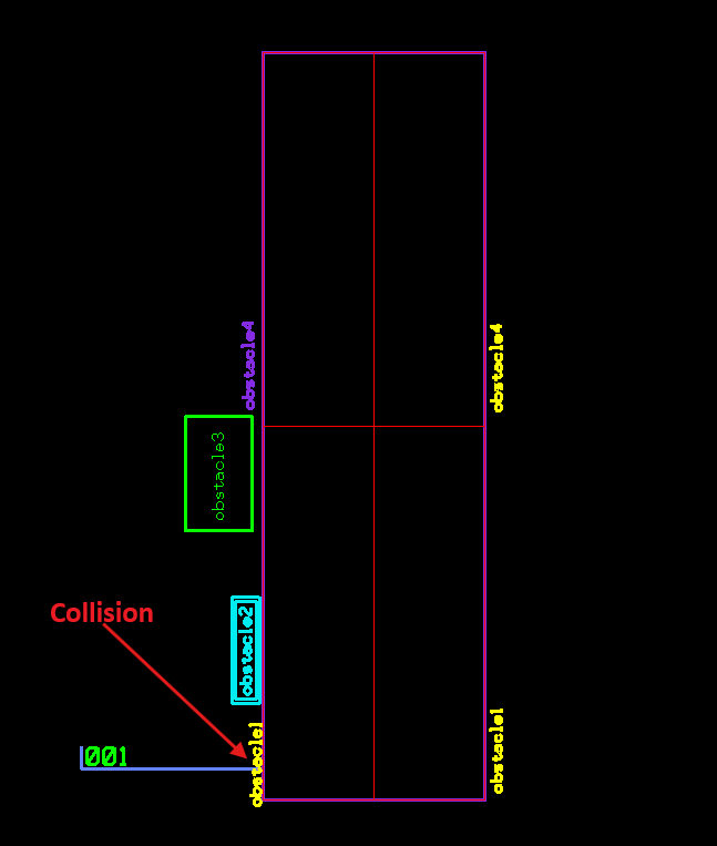
“001” Label intersects “obstacle1”
“001” label doesn’t intersect any existing items


Overview

To compute the collision-free placement of the new label for the example above we have developed a five step process outlined below using the Minkowski Sums and Convex Hulls algorithms from the Boost Geometry Library.

Quick definitions

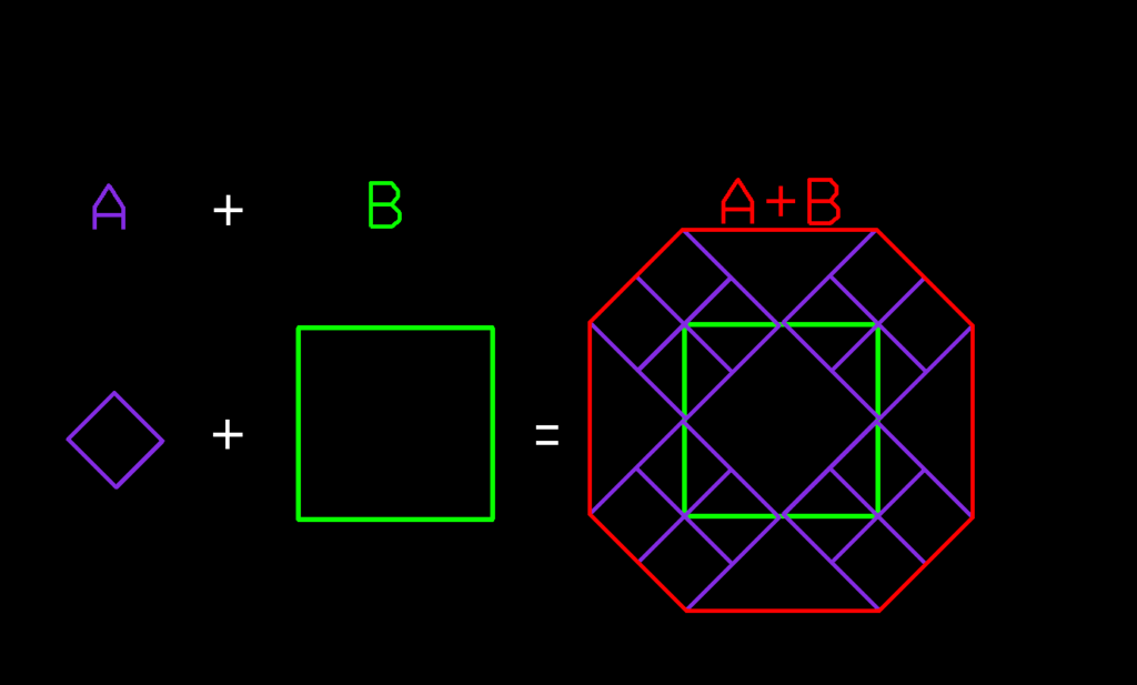
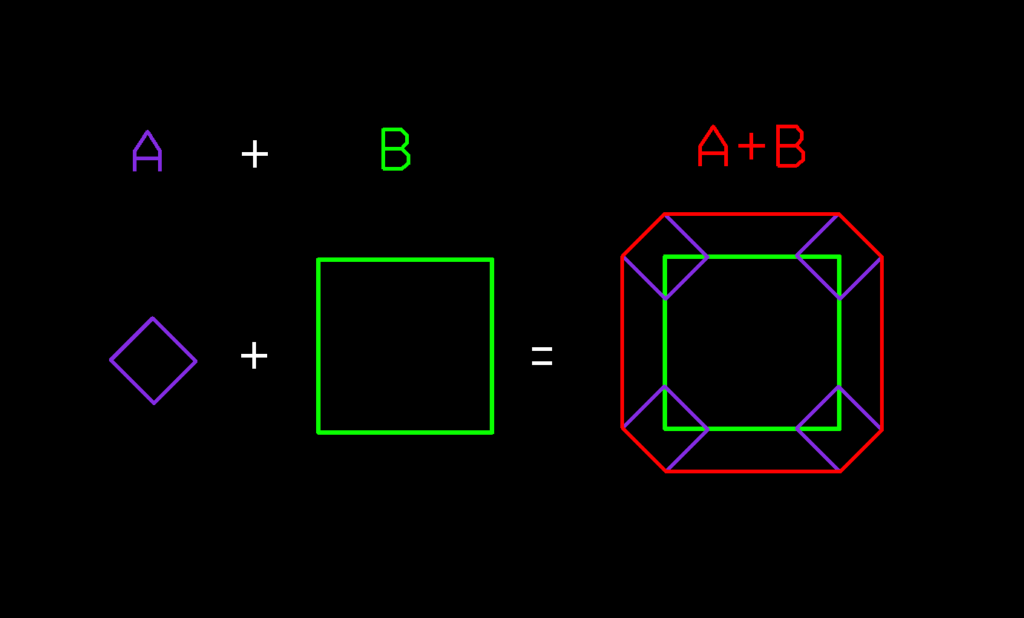
1- Minkowski Sums of two polygons is defined as a set of points computed by summing all pairs of points from the 2 polygons.

Minkowski Sums of 2 polygons A, B
Minkowski Sums of A, B with center of A as reference point

2- A convex polygon is any shape that has all interior angles that measure less than 180 degrees. A Convex Hull is the smallest convex set that contains a given shape or set of points. Boost Geometry Library implements a straightforward method to compute a Convex Hull for a set of supported geometries. Following are the Convex Hulls for our label and obstacles:

Convex Hulls of the new label and obstacles

Computing the collision-free space for the new label

We’re using the following steps to compute the collision-free space for the “001” in the example above:

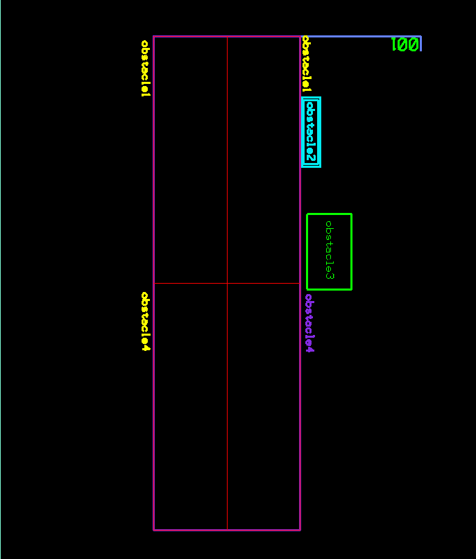
1- Translate our items to the (0,0) origin and rotate them by 180°.

Items translated to (0,0) origin and rotated by 180°

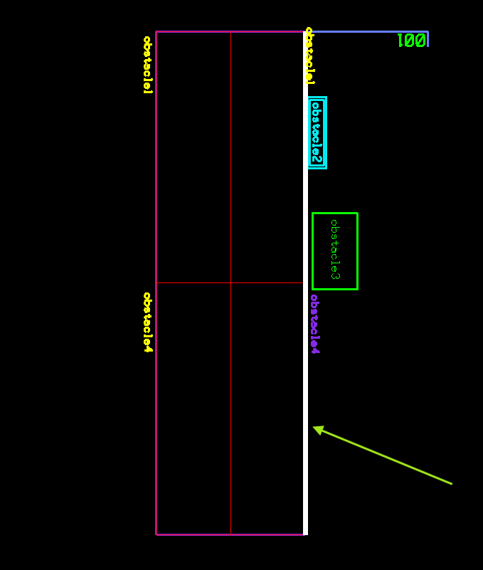
2- Extract the main placement line (shown in white below) that represents all possible placement points, with or without collision with any existing objects.

Main placement line shown in white. This represents all placement points with or without collision

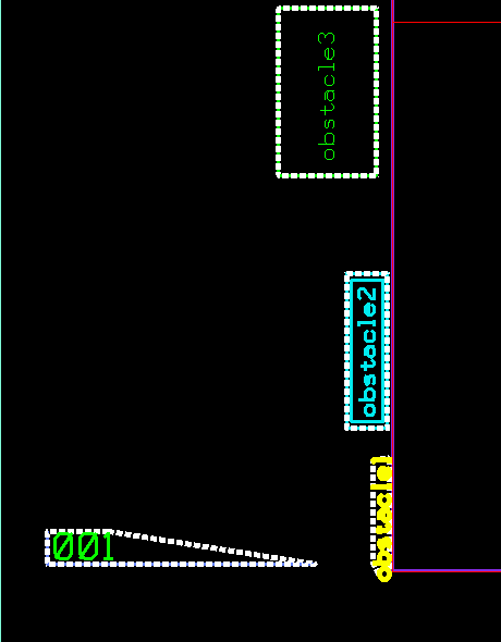
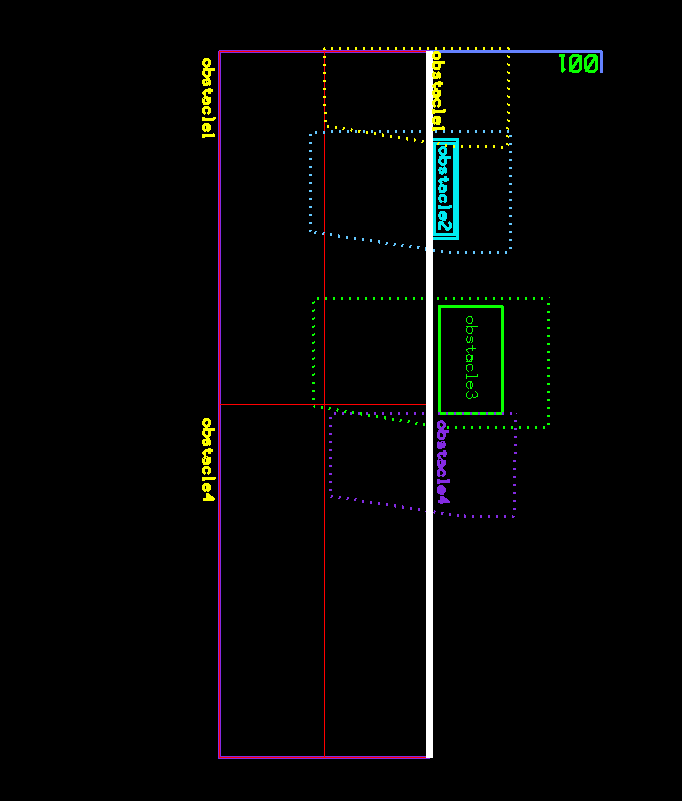
3- Compute the Minkowski Sums of the Convex hull of the “001” label with each obstacle. Results are shown in dashed polygons in the image below.

Dashed polygons being the Minkowski Sums of label and each obstacle

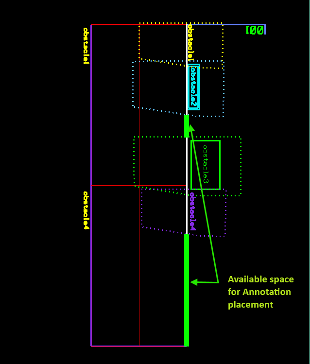
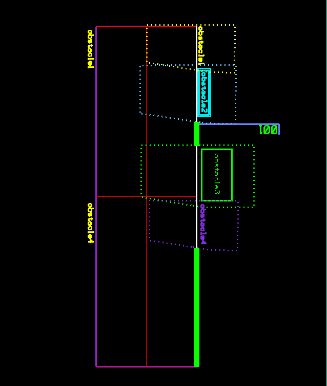
4- Clip the Minkowski Sums out of the main placement line as the resulting shapes represent the collision space.

All collision-free placement points on the 2 green segments


5- Place label on any point on the segments resulting from clipping the collision space from the main placement line (shown in green below). For simplicity, we will pick the point closest to beginning of the side line.

“001” label placed on first valid collision-free point

Sample code

Here’s sample code from Boost Geometry Library website to compute the convex hull of a polygon:

#include <iostream>

#include <boost/geometry.hpp>
#include <boost/geometry/geometries/polygon.hpp>
#include <boost/geometry/geometries/adapted/boost_tuple.hpp>

BOOST_GEOMETRY_REGISTER_BOOST_TUPLE_CS(cs::cartesian)


int main()
{
    typedef boost::tuple<double, double> point;
    typedef boost::geometry::model::polygon<point> polygon;

    polygon poly;
    boost::geometry::read_wkt("polygon((2.0 1.3, 2.4 1.7, 2.8 1.8, 3.4 1.2, 3.7 1.6,3.4 2.0, 4.1 3.0"
        ", 5.3 2.6, 5.4 1.2, 4.9 0.8, 2.9 0.7,2.0 1.3))", poly);

    polygon hull;
    boost::geometry::convex_hull(poly, hull);

    using boost::geometry::dsv;
    std::cout
        << "polygon: " << dsv(poly) << std::endl
        << "hull: " << dsv(hull) << std::endl
        ;


    return 0;
}

The following code computes the Minkowski Sums of a set of obstacle polygons using the Boost Geometry Library convolve_two_polygon_sets().

/***************************************
  Descr: Returns the Minkowski Sums between a robot and and set of obstacles
****************************************/
int mcs_minkowskiSums 
(
 std::vector<point> pts_robot,		//  => flag hull pts [MU]
 vector<VecMsPoints>	vvObstaclePts,  //  => obstacle pts [MU]
 vector<VecMsPoints>&	rvvMinSums		// <= 
)
{
	polygon_set a, b, c;
	polygon poly;
	
	removeObstacleIntersections(vvObstaclePts);

  // build polygon_set a that contains robots
	boost::polygon::set_points(poly, pts_robot.begin(), pts_robot.end());
	poly.size();
	a += poly;

   // build polygon_set b that contains obstacles
	for each (std::vector<point> pts in vvObstaclePts)
	{
		boost::polygon::set_points(poly1, pts.begin(), pts.end());
		poly1.size();
		b += poly1;
	}
 
  // Compute Minkowski Sums of the polygon sets a,b using Boost method 'convolve_two_polygon_sets'
	convolve_two_polygon_sets(c, a, b); // 

	using namespace boost::polygon;
	vector<polygon> resultPolygons;
	c.get(resultPolygons);
	
	return TRUE;
}

Conclusion

We have shown how to automatically add a new label to a CAD file without collision with existing items using Minkowski Sums and Convex hulls to find the collision space between the label and the obstacles. The application of this concept can extend beyond CAD/Collision Detection and can be used in numerous other fields such as robot motion, 3D modeling, and numerical control machining.

Mill Creek Systems, Inc provides software development services in this area. If you have any software needs, please reach out to us by clicking on the “Contact us” button below.

Contact us!

Helpful links:

Minkowski Sums Definition: https://cp-algorithms.com/geometry/minkowski.html

Introduction to Computational Geometry: https://www.geeksforgeeks.org/what-is-computational-geometry-and-how-is-it-applied-in-solving-geometric-problems

Minkowski Sums Tutorial in Boost Library https://www.boost.org/doc/libs/develop/libs/polygon/doc/gtl_minkowski_tutorial.htm

Convex Hulls https://en.wikipedia.org/wiki/Convex_polygon

Continue Reading
MENU